Page: 1
/
13
Total 65 questions
Curious about Actual Juniper Data Center Certification (JN0-281) Exam Questions?
Here are sample Juniper Data Center, Associate (JN0-281) Exam questions from real exam. You can get more Juniper Data Center Certification (JN0-281) Exam premium practice questions at TestInsights.
Question 1
Leaf and spine data centers are used to better accommodate which type of traffic?
Correct : B
In modern data centers, the shift toward leaf-spine architectures is driven by the need to handle increased east-west traffic, which is traffic between servers within the same data center. Unlike traditional hierarchical data center designs, where most traffic was 'north-south' (between users and servers), modern applications often involve server-to-server communication (east-west) to enable services like distributed databases, microservices, and virtualized workloads.
Leaf-Spine Architecture:
Leaf Layer: This layer consists of switches that connect directly to servers or end-host devices. These switches serve as the access layer.
Spine Layer: The spine layer comprises high-performance switches that provide interconnectivity between leaf switches. Each leaf switch connects to every spine switch, creating a non-blocking fabric that optimizes traffic flow within the data center.
East-West Traffic Accommodation:
In traditional three-tier architectures (core, aggregation, access), traffic had to traverse multiple layers, leading to bottlenecks when servers communicated with each other. Leaf-spine architectures address this by creating multiple equal-cost paths between leaf switches and the spine. Since each leaf switch connects directly to every spine switch, the architecture facilitates quick, low-latency communication between servers, which is essential for east-west traffic flows.
Juniper's Role:
Juniper Networks provides a range of solutions that optimize for east-west traffic in a leaf-spine architecture, notably through:
QFX Series Switches: Juniper's QFX series switches are designed for the leaf and spine architecture, delivering high throughput, low latency, and scalability to accommodate the traffic demands of modern data centers.
EVPN-VXLAN: Juniper uses EVPN-VXLAN to create a scalable Layer 2 and Layer 3 overlay network across the data center. This overlay helps enhance east-west traffic performance by enabling network segmentation and workload mobility across the entire fabric.
Key Features That Support East-West Traffic:
Equal-Cost Multipath (ECMP): ECMP enables the use of multiple paths between leaf and spine switches, balancing the traffic and preventing any one path from becoming a bottleneck. This is crucial in handling the high volume of east-west traffic.
Low Latency: Spine switches are typically high-performance devices that minimize the delay between leaf switches, which improves the efficiency of server-to-server communications.
Scalability: As the demand for east-west traffic grows, adding more leaf and spine switches is straightforward, maintaining consistent performance without redesigning the entire network.
In summary, the leaf-spine architecture is primarily designed to handle the increase in east-west traffic within data centers, and Juniper provides robust solutions to enable this architecture through its switch platforms and software solutions like EVPN-VXLAN.
Start a Discussions
Submit Your Answer:
Question 2
Which two statements describe an IP fabric? (Choose two.)
Correct : C, D
An IP fabric is a network topology designed to provide a scalable, low-latency architecture that is typically implemented in modern data centers. It uses spine and leaf switches and enables efficient traffic load sharing across the network.
Step-by-Step Breakdown:
Spine-Leaf Architecture:
Leaf Devices: These switches connect to servers and edge devices within the data center. Each leaf switch connects to every spine switch.
Spine Devices: These high-performance switches interconnect all the leaf switches. There are no direct connections between leaf switches or spine switches. This architecture ensures that any two endpoints within the fabric are only one hop away from each other, minimizing latency.
Traffic Load Sharing:
An IP fabric leverages Equal-Cost Multipath (ECMP) to distribute traffic evenly across all available paths between leaf and spine switches, providing effective load balancing. This ensures that no single link becomes a bottleneck and that traffic is distributed efficiently across the network.
Juniper Reference:
Juniper provides QFX Series switches optimized for IP fabric topologies, allowing for scalable deployments in modern data centers.
EVPN-VXLAN: Often used in IP fabrics to extend Layer 2 services across the fabric with Layer 3 underlay, enabling both efficient routing and bridging.
Start a Discussions
Submit Your Answer:
Question 3
What is the primary purpose of an IRB Layer 3 interface?
Correct : C
The primary purpose of an IRB (Integrated Routing and Bridging) interface is to enable inter-VLAN routing in a Layer 3 environment. An IRB interface in Junos combines the functionality of both Layer 2 bridging (switching) and Layer 3 routing, allowing devices in different VLANs to communicate with each other.
Step-by-Step Breakdown:
VLANs and Layer 2 Switching:
Devices within the same VLAN can communicate directly through Layer 2 switching. However, communication between devices in different VLANs requires Layer 3 routing.
IRB Interface for Inter-VLAN Routing:
The IRB interface provides a Layer 3 gateway for each VLAN, enabling routing between VLANs. Without an IRB interface, devices in different VLANs would not be able to communicate.
Configuration:
In Juniper devices, the IRB interface is configured by assigning Layer 3 IP addresses to it. These IP addresses serve as the default gateway for devices in different VLANs.
Example configuration:
set interfaces irb unit 0 family inet address 192.168.1.1/24
set vlans vlan-10 l3-interface irb.0
This allows VLAN 10 to use the IRB interface for routing.
Juniper Reference:
IRB Use Case: Inter-VLAN routing is essential in data centers where multiple VLANs are deployed, and Juniper's EX and QFX series switches support IRB configurations for this purpose.
Start a Discussions
Submit Your Answer:
Question 4
Exhibit:
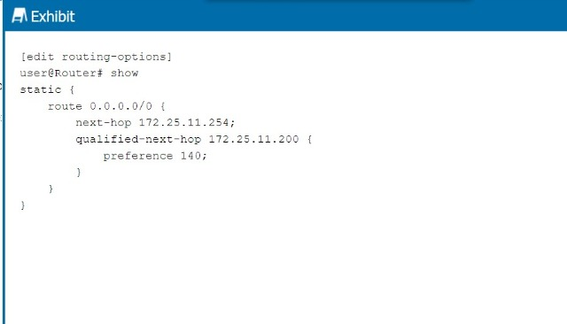
Referring to the exhibit, what is the route preference of the 172.25.11.254 next hop?
Correct : A
In the exhibit, we see two next-hop addresses for the default static route (0.0.0.0/0):
The first next hop is 172.25.11.254, with no specified preference.
The second next hop is 172.25.11.200, with a specified preference of 140.
Step-by-Step Breakdown:
Default Static Route Preference:
If no preference is explicitly set for a next hop in Junos, it defaults to 5 for static routes.
Determining Preference:
In this case, the next hop 172.25.11.254 does not have an explicit preference defined, so it will use the default value of 5. The second next hop has a preference of 140, which is higher, meaning it will only be used if the primary next hop is unavailable.
Juniper Reference:
Static Route Preference: In Junos, the default preference for static routes is 5, and this value is applied unless overridden by the preference parameter.
Start a Discussions
Submit Your Answer:
Question 5
When troubleshooting an OSPF neighborship, you notice that the router stopped at the ExStart state. What is the cause of this result?
Correct : D
When an OSPF (Open Shortest Path First) neighborship is stuck in the ExStart state, it usually points to a mismatch in Maximum Transmission Unit (MTU) settings between two routers trying to establish the adjacency. The ExStart state is where OSPF routers negotiate the master-slave relationship and exchange DBD (Database Description) packets.
Step-by-Step Breakdown:
OSPF Neighbor States: OSPF goes through several states to establish an adjacency with a neighbor:
Down: No hello packets have been received.
Init: Hello packets are received, but bidirectional communication isn't confirmed.
2-Way: Bidirectional communication is established.
ExStart: The routers are negotiating who will be the master and who will be the slave, and begin to exchange DBD packets.
Exchange: The routers start exchanging the database information.
Loading: The routers process the Link-State Advertisements (LSAs).
Full: The adjacency is fully established.
MTU Mismatch Issue:
During the ExStart state, both OSPF routers must agree on their MTU values. If there is an MTU mismatch between the two routers, OSPF neighbors will fail to move from the ExStart to the Exchange state. The router with the larger MTU setting will not accept DBD packets from the router with a smaller MTU because the packets may exceed the smaller MTU size.
In Juniper devices, this behavior can be identified by examining the MTU settings using the show interfaces command and ensuring both routers have matching MTU configurations. To resolve this issue, either match the MTU settings on both routers or configure OSPF to ignore MTU mismatches using the command set protocols ospf ignore-mtu.
Juniper Reference:
Junos Command: show ospf neighbor helps diagnose neighbor states.
MTU Adjustment: set interfaces <interface-name> mtu <size> can be used to set the MTU values correctly.
Start a Discussions
Submit Your Answer: